Printed Circuit Boards
Printed circuit boards (PCBs) are the backbone of all electronics. They provide the power needed to run various devices, from wearables and medical equipment to industrial machines. However, despite their importance, circuit boards are not immune to failure and can develop a wide range of malfunctions from the time they leave the factory until they reach the end user. Fortunately, these problems can be identified and remedied with proper diagnostics and maintenance.
The main reason for quick turn circuit boards failure is due to mechanical stress. This can be caused by vibrations, bending, or shocks, as well as electrical overloading. Additionally, components can break down over time due to age-related deterioration or poor manufacturing quality.
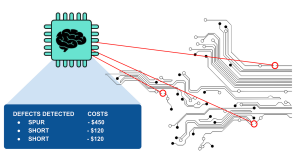
Another cause of PCB failure is due to soldering defects, which can result in short circuits or connectivity issues. These issues can be caused by cold solder joints, loose connections, or a lack of adequate heat dissipation. In some cases, these defects are not visible and can only be detected by a thorough inspection.
Common Failure Modes Associated With Printed Circuit Boards
Other common reasons for a quick turn PCB to fail include EMI/EMC interference and circuit board design errors. These mistakes often occur because of a lack of experience in designing PCBs, or they may be the result of inadequate tools for the job. For example, a mistake in choosing the correct trace width can lead to EMI/EMC interference or poor performance, while a miscalculation in routing can result in broken tracks and connections.
Mechanical defects can also cause a quick turn PCB to fail. These can be caused by physical stresses such as bending, vibrations, or shocks, as well as electrical issues like overloading and high-voltage spikes. These defects can be difficult to identify and fix, but they can be prevented by using a comprehensive quality inspection and maintaining detailed documentation of the production process.
Chemical leakage is a serious issue that can damage and even destroy a circuit board. This is due to the chemicals used in the etching process leaching out over time and causing corrosion on other parts of the board. Another cause of this type of problem is the use of improper components in the assembly process, which can lead to physical damage to the board or a lack of connections between components.
Conductive anodic filaments (CAFs) can form in a PCB due to the presence of moisture and other contaminants. These filaments are a product of electrochemical migration, and they grow along the resin glass interface from the anode to the cathode sub-surface. This problem is exacerbated by the use of lead-free solders, which require a higher soldering temperature than traditional lead solders.
Lastly, mechanical defects can also cause a quick turn PCB failure. These can be the result of poor design, improper handling, or shipping. Some of these defects can be resolved by reworking the component or replacing it entirely, while others will require a complete replacement of the board. To prevent these defects, manufacturers must use a strict quality inspection process that includes Destructive Physical Analysis, which involves sacrificing a sample of the board.